FMOS Furniture Manufacturing Operating System
Furniture Manufacturing Operating System

Draw Rooms. Configure Modules. Ship to Factory.

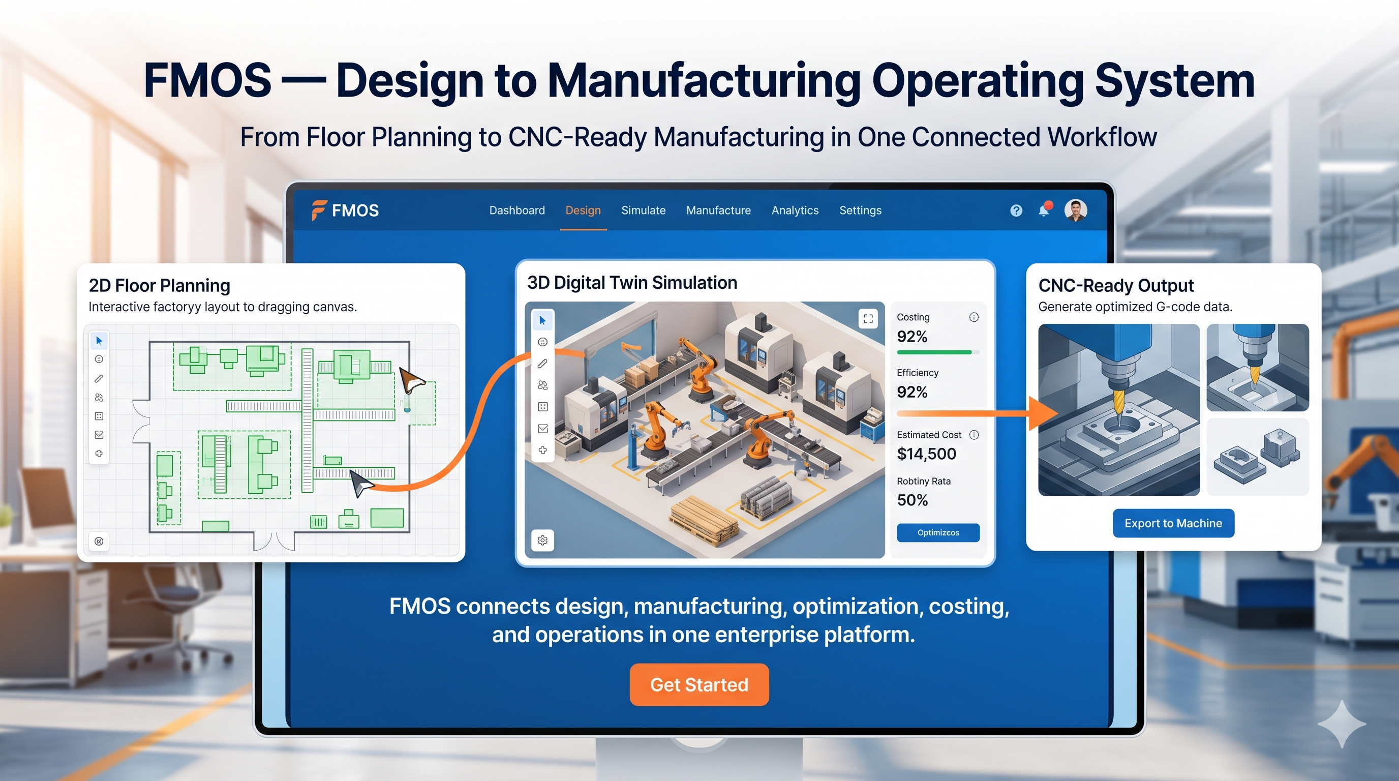
FMOS is a complete design-to-manufacturing platform for modular furniture studios and production factories. Draw your floor plan in 2D, switch to a live 3D preview, configure modules with rule-driven manufacturing logic, and export cutlists, BOMs, panel labels, and CNC-ready files — all from one connected workflow.

One system from the first wall drawn to the last CNC file exported. No spreadsheets, no re-keying, no disconnected tools.

2D CAD Canvas 3D Visualization Floor Plan Auto-Detect Cutlist + BOM DXF / G-code Export Team Collaboration

FMOS product preview

2D + 3DOne canvas, two views
31+ modulesRule-driven, wall-snapped
DXF + G-codeMachine-ready CNC output
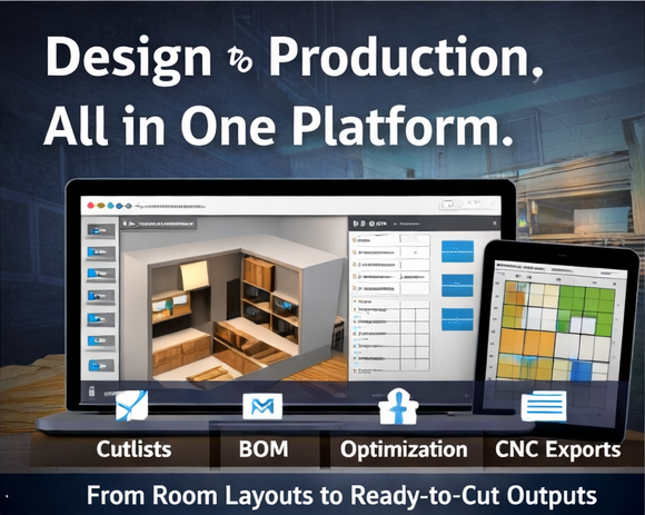
FMOS furniture manufacturing software workspace showing design to production workflow
Design to production
FMOS cutlist optimizer dashboard highlighting BOM, cutlists, and CNC-ready files
Cutlists, BOM and CNC
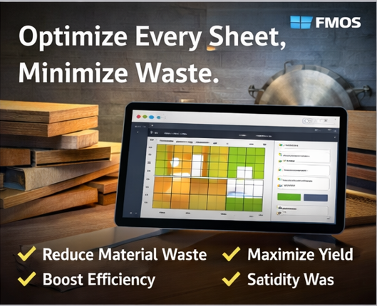
FMOS plywood cutting optimization interface focused on sheet yield and waste reduction
Optimization and yield
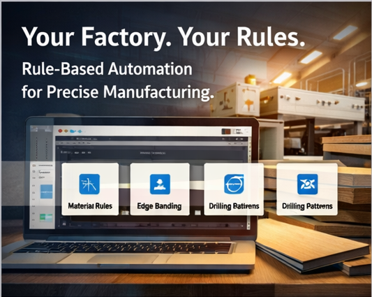
FMOS cabinet manufacturing software screen for material, edge banding, and drilling rules
Rule-based automation
Draw walls → auto-detect roomsCanvas
Rule engine → panels + edge bandsRules
Guillotine nesting → sheet layoutYield
Cutlist + BOM + DXF / G-codeOutput

The gap between design approval and factory floor costs you time and money

Most furniture teams still hand-build the same job twice — once for the client, again for the workshop. Every re-keying step risks an error. Every tool boundary loses context.

FMOS is built for studios and factories that need design intent to flow directly into manufacturing data — without an interpreter in the middle.

  • Room layouts are approved in one tool and manually re-entered for production in another.
  • Panel dimensions and edge-band specs are calculated by hand from drawings that were never meant for manufacturing.
  • Sheet-nesting happens too late — after cutting has already started — because there was no optimization step in the workflow.
  • Workshop teams wait for clarity on dimensions, materials, and quantities that should have been locked at the design stage.

Design and production live in different systems

Approved layouts are rebuilt for manufacturing instead of flowing forward automatically from the same data.

Panel lists assembled by hand

Cutlists, BOM figures, and edge-band specs depend on manual interpretation instead of a rule engine that never forgets.

Sheet yield left on the table

Plywood nesting is guesswork without an optimization step that fits all panels onto sheets before the first cut.

CNC operators waiting for files

Machine-ready DXF and G-code outputs should be a by-product of the design stage, not a separate effort that happens after everything else.

One closed pipeline from floor plan to factory output

FMOS owns the full chain. Every panel produced is traceable to a module, a manufacturing rule, a material, and a project. No external drawings, no import dependencies, no re-keying.

The pipeline is deliberately closed: you design inside FMOS, so the manufacturing data is always consistent with the design intent. Every downstream output — panels, BOM, cutlist, CNC file — is computed, not typed.

Step 1 — DrawBuild your spatial model on the canvas

Draw walls, doors, and windows on the 2D CAD canvas. Or upload a floor plan image — FMOS auto-traces walls and detects rooms with OpenCV. The result is a structured Building → Floor → Room → Wall hierarchy, ready for modules.

Step 2 — ConfigurePlace modules with manufacturing rules enforced

Choose from 31+ parametric module types and snap them to walls. Compose custom furniture in the section-based designer. Assign materials, laminates, and manufacturing rules. Every choice is recorded — not estimated later.

Step 3 — ManufactureGenerate every factory output in one click

Trigger panel generation, run Guillotine sheet-nesting optimization, build the BOM, and export DXF/G-code for CNC and labelled panel sheets for the shop floor — all derived from the same project data.

Every shipped feature — no marketing inventory

All capabilities listed here are in production. Nothing on this list is a roadmap item.

2D CAD canvas

Draw walls, doors, and windows with endpoint snap, angle snap, grid snap, and automatic corner joins. Wall thickness renders accurately. Room shapes are traced in real time as you draw.

Floor plan auto-detection

Upload an existing floor plan image and FMOS traces walls and detects room outlines using OpenCV. Detected rooms are validated, scaled, and added to the project hierarchy automatically.

3D visualization and presentation

Switch from 2D canvas to a live Three.js 3D view at any point. Orbit, frame, and apply quality tiers for client-facing presentations — walls, doors, windows, and modules all render with material textures.

31+ parametric module library

Kitchen base, wall, and tall units; wardrobes, TV units, storage modules, and more. Each type is configured by width, height, and depth. Modules snap to walls and dimensions are validated against wall constraints.

Custom furniture section composer

Build bespoke pieces using a section-based visual designer. A 47-rule constraint evaluator validates each configuration — drawer stacks, shelves, hanging rods, and tier combinations. Save the result as a reusable module template.

Manufacturing rule engine

Every module type maps to a manufacturing rule that resolves panel geometry, axis orientation, edge-band assignments, and BOM line items. Rules are configurable, version-tracked, and support per-material exclusions.

Automatic panel generation

One API call generates all panels for a module from its rule definition. Panel labels are assigned automatically for shop-floor tracking. Panels are invalidated and cutlists marked stale when upstream modules change.

Guillotine sheet-nesting and cutlists

A Guillotine nesting algorithm fits all project panels onto standard 2440×1220mm sheets, maximising yield. Cutlists show part IDs, sheet placements, and dimensions. An async background worker handles large projects without timeouts.

BOM, CNC export, and panel labels

Generate project and per-module BOMs with cost snapshots. Export DXF and G-code files for machine-ready cutting (48h secure storage with signed download URLs). Print panel labels with part identifiers for shop-floor assembly tracking.
Built for the metrics that matter in furniture production

FMOS removes the manual work at each stage of the design-to-manufacturing pipeline, so every team — designers, estimators, and workshop operators — starts with accurate, consistent data.

Eliminate design-to-production re-keying

Room dimensions, module configurations, and material choices flow forward through the pipeline — they are never retyped into a second tool.

Improve sheet yield before the first cut

Run Guillotine nesting optimization while the project is still in design. Act on sheet utilization before material is committed, not after.

Lock manufacturing rules per module type

Panel geometry, edge-band specs, and hardware requirements are resolved by the rule engine — not interpreted differently by each estimator or operator.

Deliver machine-ready files as a workflow by-product

DXF and G-code exports are generated from the same project data that produced the BOM and cutlist. No separate CAM step, no reformatting.

What is coming next

The platform is in active development. These items are in progress or planned — none are shipped yet.

In ProgressAI layout recommendations

A Python intelligence sidecar is wired to the layout engine and will surface module placement and room-configuration suggestions based on room geometry and project history.

PlannedProduction floor tracking

Connect the cutlist to a live job status board: cutting → edge-banding → assembly → QC → dispatch. Give factory supervisors visibility from one screen.

PlannedHardware fittings BOM

Extend the manufacturing bill-of-materials beyond panels and edge bands to include hinges, drawer systems, handles, and other hardware mapped from module rules.

PlannedClient-facing project portal

Share a read-only project view with clients — 3D renders, module selections, and cost summaries — without exposing internal manufacturing data.

PlannedMobile-optimised site visits

A field-accessible view for on-site measurements and module placement review, optimised for phones and tablets on the job site.

PlannedAdvanced quotation workflows

Turn project BOMs into client-ready quotations with margin controls, GST line items, and approval tracking — without leaving FMOS.

Who FMOS is built for

FMOS fits teams where design intent must flow directly into manufacturing data — without interpretation, re-keying, or tool switching.

Modular furniture studios with in-house factories

One system covers client-facing design (2D + 3D), manufacturing rule application, sheet optimization, and CNC output — all on the same project record.

Kitchen and wardrobe manufacturers

Place wall-snapped base, wall, and tall modules, assign standard or custom laminates, generate panels and cutlists, and export DXF for your CNC without leaving the browser.

Multi-designer studios and production teams

Invite designers, admins, and viewers into a shared org. Role-based access controls what each team member can design, approve, or export. Subscription plan limits scale with the team.

Owner-led custom furniture workshops

Build bespoke pieces in the section composer, save them as module templates, and reuse the same configurations across multiple client projects without starting from scratch.

How different teams use FMOS

The same pipeline adapts to kitchen studios, wardrobe manufacturers, full-home interior contractors, and multi-project production teams.

Modular kitchen production

Draw the kitchen walls, place base/wall/tall units against them, assign core and finish materials, run sheet optimization, and hand the CNC operator a DXF file — without a single spreadsheet in the chain.

Wardrobes and sliding storage

Use the section composer to define the internal layout — shelves, drawers, hanging rods — then generate panels, edge bands, and a labelled cutlist for every carcass in the project.

Full-home interior contracts

Manage multiple rooms (kitchen, bedrooms, living area) under one project. The hierarchy keeps each room's modules, materials, and manufacturing data separate but the BOM and optimization can run across the entire project.

Office fit-outs and commercial interiors

Multi-floor, multi-room projects are structured under one building record. Each floor has its own rooms and module configurations, with a consolidated project BOM and optimization run.

Where FMOS changes the numbers

The gains come from removing the manual steps between stages — not from optimizing any single step in isolation.

Output speedPanels from modules in secondsRule engine resolves panel geometry and edge bands the moment a module is configured — no calculation step.
Sheet yieldGuillotine nesting before cuttingRun optimization while the design is still editable. Adjust modules or quantities and re-optimize — no material committed yet.
Data accuracyOne source of truth, zero re-keyingDimensions, materials, and rules set at the design stage produce the BOM, cutlist, and CNC files — nothing is retyped downstream.
Team scaleRole-based multi-user accessOwner, admin, designer, and viewer roles let the team work concurrently on the same project without stepping on each other.
No design-to-factory translation step

The manufacturing data is a direct output of the design choices. The designer and the factory operator are working from the same record.

Cutlists that stay current automatically

When a module changes, its panels are flagged and the cutlist is marked stale. The next generation picks up the updated data — no manual reconciliation.

Material and cost config locked per project

Sheet rates, edge-band rates, and hardware costs are stored inside the project record, not in a shared spreadsheet that drifts between jobs.

Scalable across multiple projects and users

Multi-tenant org structure with subscription plan limits means one account covers the full team, with usage controls that grow as the business does.

What makes FMOS different

FMOS is not a CAD tool with a cutlist add-on. It is a parametric, rule-driven manufacturing OS built so that the design and the factory output are the same object.

Import-based tools (SketchUp + CutRite, AutoCAD + nesting software)
  • Design in one tool, re-export to another for manufacturing.
  • Panel dimensions are entered manually or inferred from geometry — error-prone at scale.
  • Rule logic (edge bands, panel types) lives in the operator's head or a separate spec sheet.
  • Any design change requires re-exporting and re-processing the manufacturing data.
  • Sheet nesting, BOM, and CNC files are produced by different people in different tools.
FMOS — closed parametric pipeline
  • No DXF import. All design happens inside FMOS, so the manufacturing data is always consistent with the design.
  • Every panel is generated by the rule engine from module definitions — dimensions are never typed by hand.
  • Edge bands, material specs, and hardware assignments are resolved automatically per module type.
  • Change a module dimension and the panels, BOM, and cutlist update in the next generation — no re-export needed.
  • Guillotine nesting, BOM, panel labels, and DXF/G-code are all produced from the same project record.

Early feedback from pilot teams

We are replacing these placeholders with verified customer quotes as pilot projects complete. If you are running FMOS in your factory and want to share feedback, reach out.

"The moment we saw the cutlist come out of the same screen we designed in — that was the whole pitch."

Production LeadPilot user, Modular Kitchen Studio

"We used to take two days to prep a full-home project for the workshop. With FMOS the handoff is the same afternoon."

FounderPilot user, Custom Interior Workshop

Start free. See the full pipeline in your first project.

Create a project, draw a room, place a module, run optimization, and export a cutlist — all in one session. No setup calls, no credit card required to start.

For studios and factories evaluating FMOS

The free trial gives you access to the full pipeline: 2D CAD canvas, floor plan auto-detection, 3D visualization, module library, manufacturing rules, sheet optimization, and CNC export. Run a real project from your current backlog — not a synthetic demo.

  • Draw or upload a floor plan for an active client project.
  • Place modules, assign materials and rules, and run optimization.
  • Export the cutlist and DXF and compare them against your current process.
For teams that want a guided rollout

If you want a walk-through of the full pipeline — floor plan to CNC export — for your specific product type (modular kitchen, wardrobe, full-home), reach out to book a session. We will work through a real project from your factory, not a scripted demo scenario.